NASA's Perseverance rover is a remote controllable rover designed to explore the surface of the Red Planet. The rover primarily uses an ultra-high frequency antenna to communicate with Earth. Data is relayed through Mars satellites back to Earth where engineers can monitor the robot's trajectory and speed.
Although my robot is not designed for Mars, it is designed to explore the outer reaches of my kitchen and living room while I am comfortably relaxing in my bedroom. Instead of orbitting satellites I use my WiFi network and communicate with my robot using http requests. This project is intended to emulate a remote controlled rover such as Perserverence, using my own circuit and software designs.
- Must be able to drive in any direction
- Programmed in C/C+
- Non-arduino based coding envrionment
- Battery powered
- Map "WASD" keys to driving direction
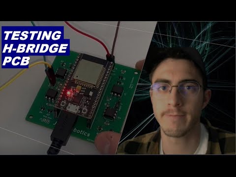
- All electronics contained on one PCB
- Remote controlled using video feed
- Lag between key presses and robot response < 0.5 s
- ESP 32 microcontroller programmed in Arduino
- 2 wheels/motors in the rear (RWD)
- 1 wheel/motor in the front
- esp32CAM for video streaming
- Plexiglass chassis
- ESP32 programmed in Expressif IoT Development Framework
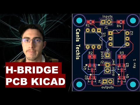
- PCB designed in KiCAD and fabricated by JLC PCB
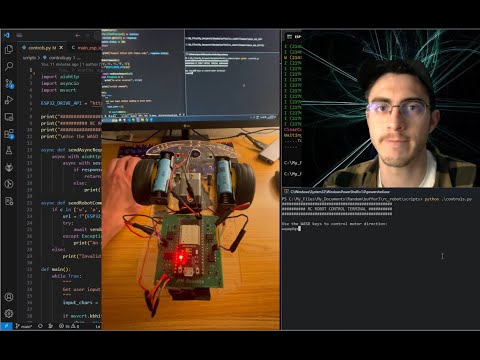
- control terminal for WASD keys written in Python
| Task | Deadline |
|---|---|
| get 3D printer working | Nov.19 (Sat) |
| receive MOSFETs | Nov.19 (Sat) |
| get H-bridges working | Nov.20 (Sun) |
| test singular power source with capacitor | Nov.20 (Sun) |
| finish PCB design and send order for fab | Nov.27 (Sun) |
| make CAD drawing for chassis and 3D print | Dec.4 (Sun) |
| receive PCB | Dec.7 (Wed) |
| solder components on PCB and test | Dec.11 (Sun) |
| finish all software | Dec.18 (Sun) |

- even though a motor draws 0.2 A while running it can produce a stall current of 2+ A, causing the driver to underpower the arduino
- meaured the 5V output of the Arduino and saw the voltage hang around 3 V sometimes dropping even lower as the motors change directions. I need to either put the motors on a separate power supply or use large capacitors to buffer voltage spikes
- After doing some research I found out that the larger the current draw is from the battery, the lower the batteries output voltage will be due to the internal voltage drop. Batteries have an internal resistance, so the larger the current out of the battery, the larger the internal drop, and the lower the output voltage will be. Hypothesis, to solve this, use batteries with larger capacity, such as two 18650's in series, which have a combined 2800mAh capacity. Results: it worked!
- Got video streaming over Bluetooth by changing ArduCAM's serial prints to use SerialBT, then using a BT virtual COM port for the host app
- Tried combining all the camera source code, bluetooth serial, http webserver, and motor controls all in one program, but the program is too large for the ESP32. Further, I do not want the camera streaming software to be delayed by running motor controls and http server responses in the same control loop. I could use FreeRTOS to split up these tasks, but that seems overkill. There is no need to have all this code on one processor when I can buy an integrated esp32-CAM that I can dedicate to video streaming. Having the robot be controlled over WIFI is also superior to Bluetooth as it allows me to operate the vehicle compleletely remotely as long as I have the WIFI router's IP address and port forwarding setup.
- Do a beep test on a PCB before placing components
- DO NOT POWER UP PCB UNTIL YOU ARE SURE EVERYTHING IS CONNECTED PROPERLY
- BE VERY SURE you don't mix up power and ground, as reversing the polarity will surely fry your components
- If hand soldering a PCB, do it in stages, and test each module individually as you go